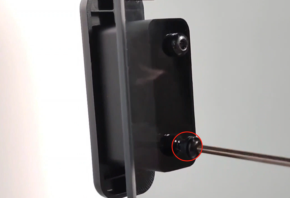
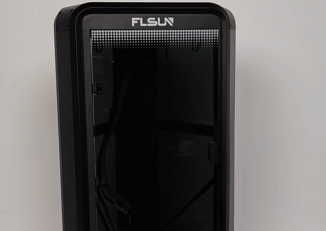
¶ Unpacking and assembly reference video:
¶ Unpacking and assembly specific steps:
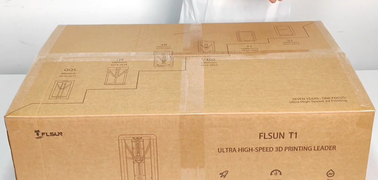
¶ 1. Unpack the box and check the instruction manual packing list to ensure that the spare parts are complete.
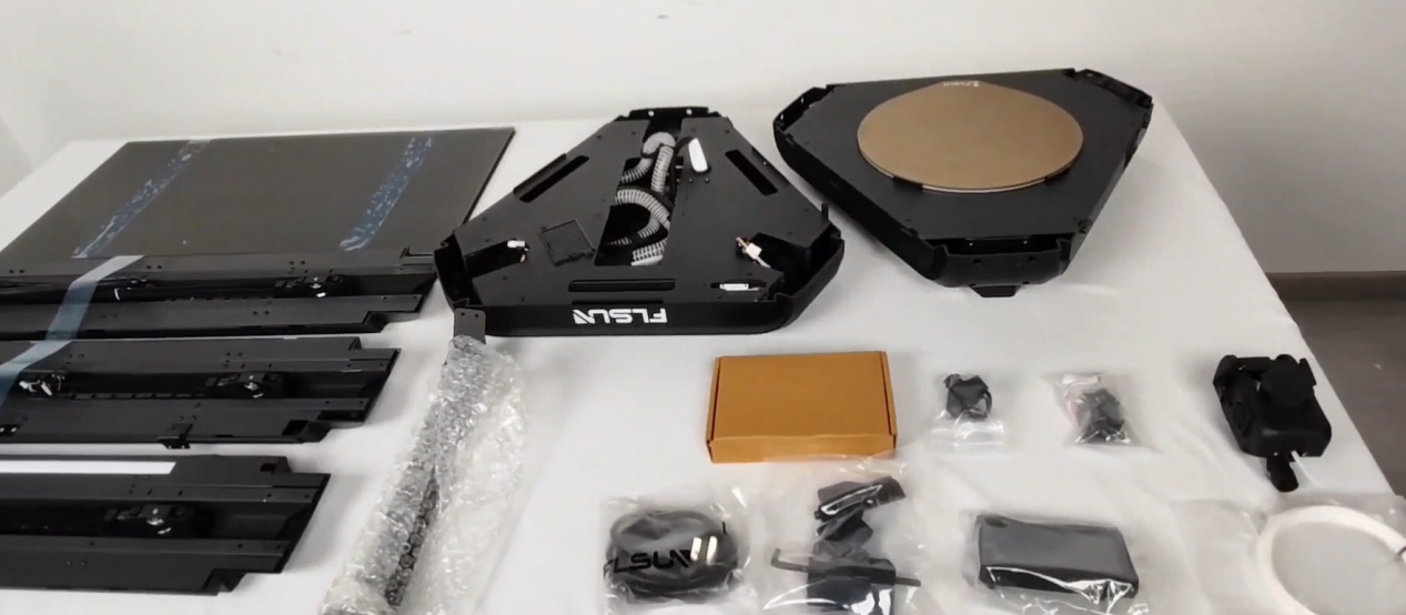
¶ 2. Take out the upper shell,filament bracket and M3×6*4 screws, and turn the upper shell upside down on the table as shown.
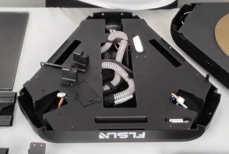
¶ 3. Align the filament bracket with the screw hole of the upper shell and fix it with M3×6 screws.
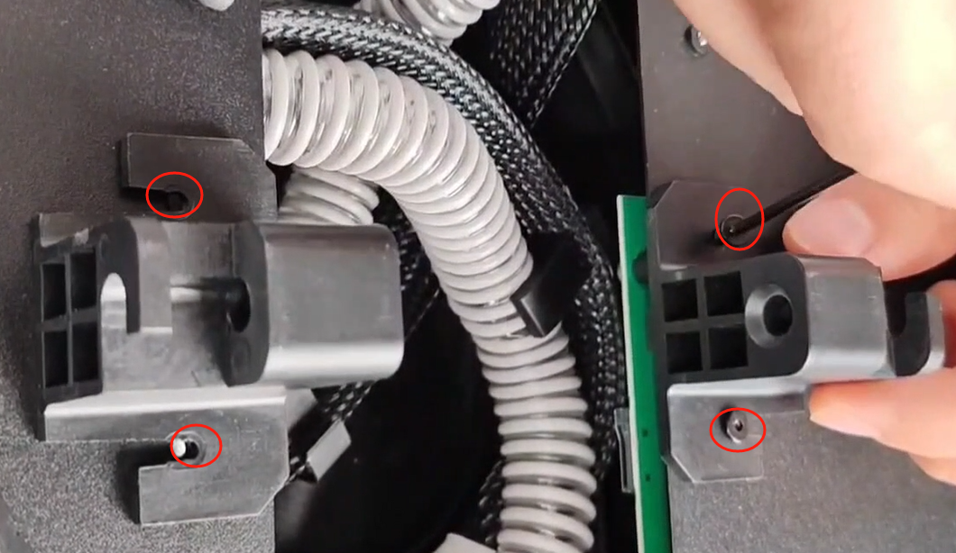
¶ 4. Insert the filament bracket pin into the consumable bracket in the direction shown in the figure.

¶ 5. Take out the cable in the sidemost groove.
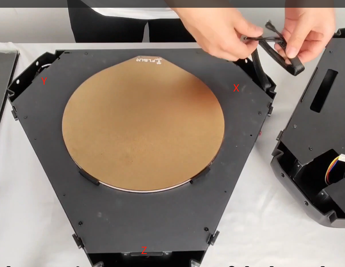
¶ 6. Tear off the tape on the three columns and remove the belt fixing clip
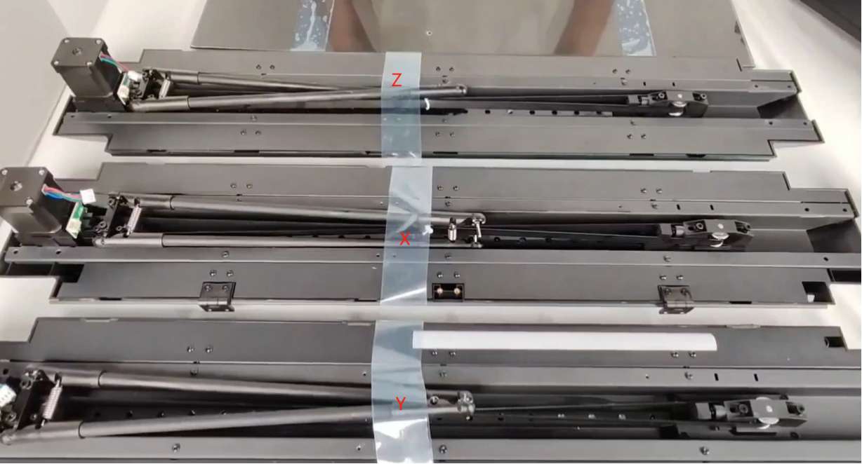
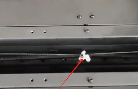
¶ 7. Place the X, Y, and Z columns in the corresponding grooves.
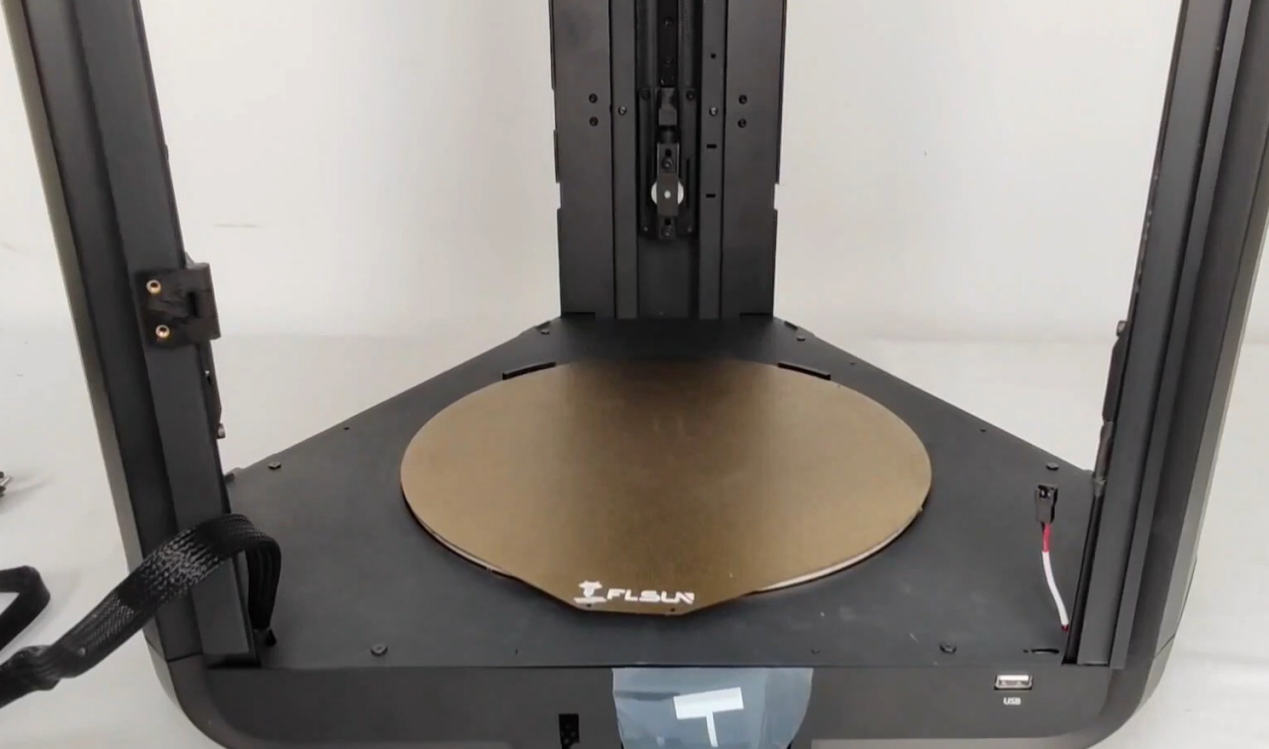
¶ 8. Place the upper shell, pay attention to the direction and position, the logo icon on the upper shell is on the same side as the screen position of the lower shell, which is the front.
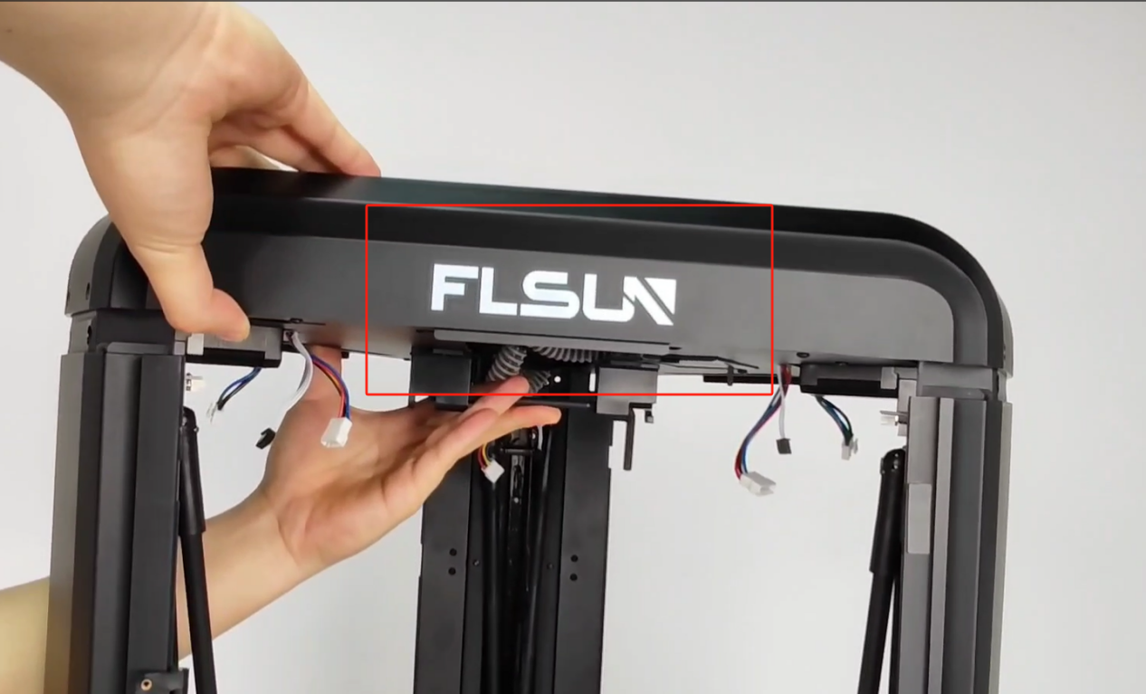
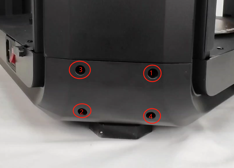
¶ 9. Use M4×12 screws to fix the upper and lower shells and the three shafts. First tighten the fixing screws of the lower shell and the three shafts, and then tighten the fixing screws of the upper shell and the three shafts (tighten diagonally in the order shown in the figure).
¶ 10. Pre-fix the M3×5 and M3×3 screws to the effector's hanging platform for 1-2 turns.
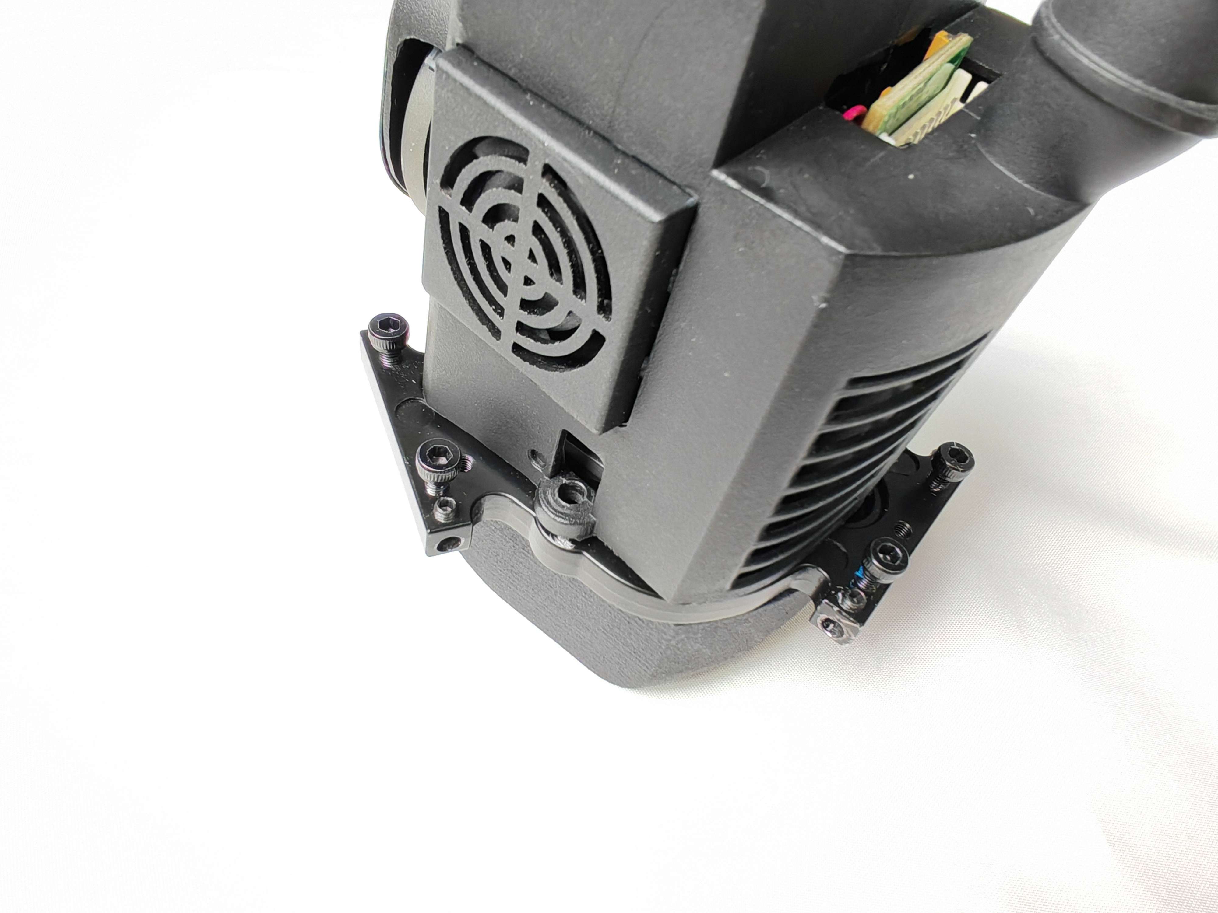
¶ 11. Install the effector, and make sure the logo faces forward.
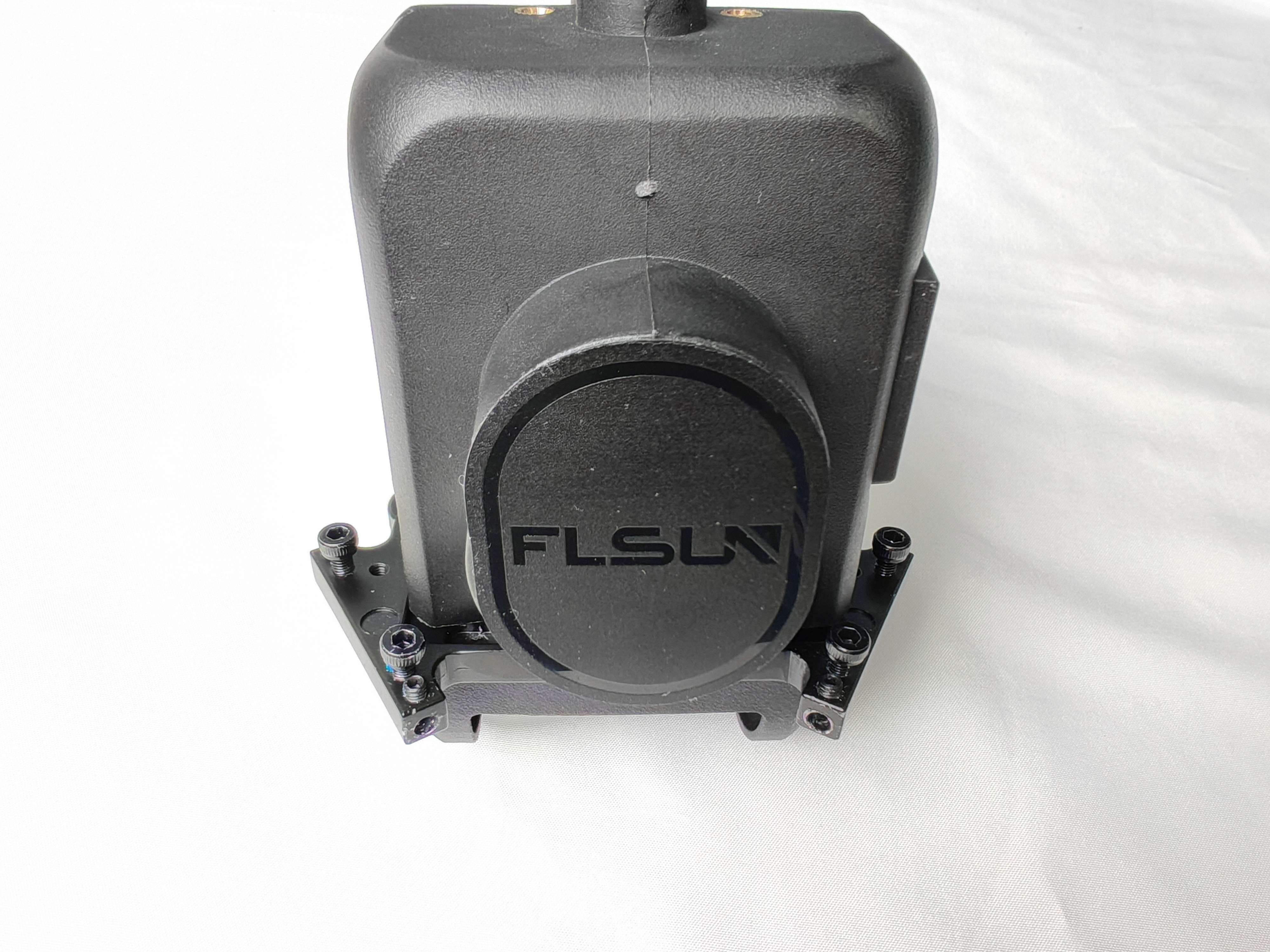
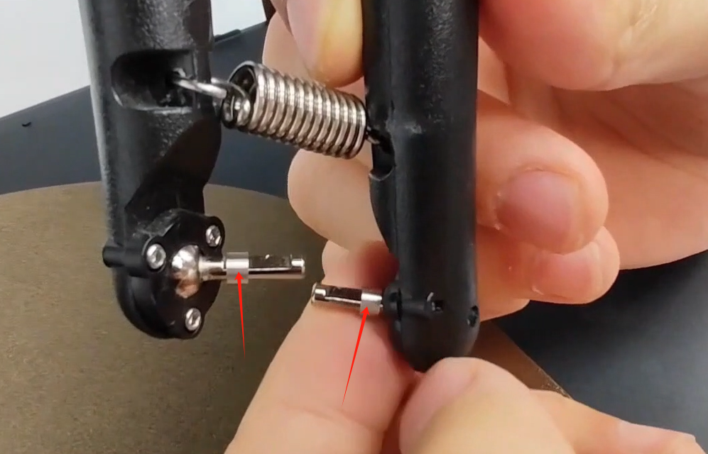
¶ 12. Install the isolation column on the parallel arm ball pin.
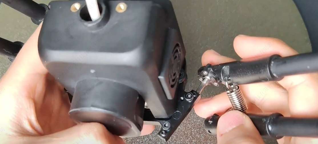
¶ 13. Insert the parallel arm ball pin into the hanging platform and tighten the screw. (Note that the parallel arm ball pin plane faces upward), and the other 5 parallel arms are fixed in this way in turn.
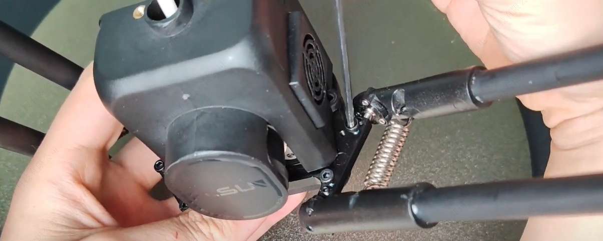
¶ 14. Remove the effector line and air duct from the upper shell, and cut off the tie.
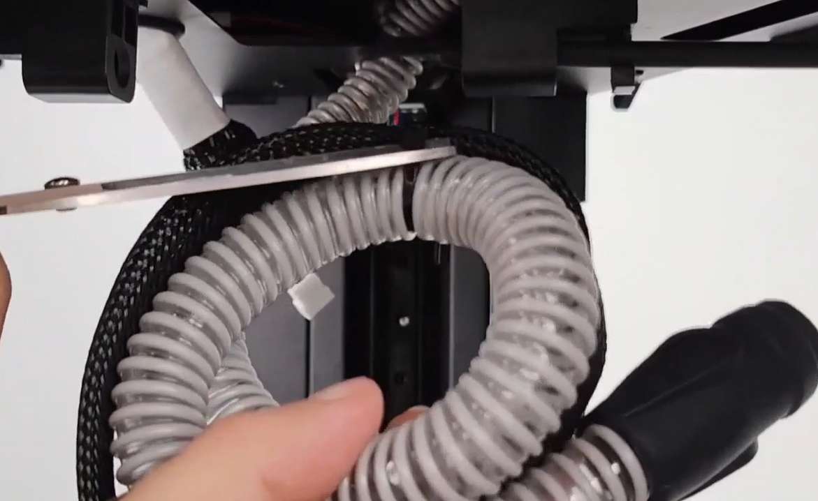
¶ 15. Align the air duct with the interface on the effector and press it down. Be careful not to twist the air duct to prevent it from breaking.
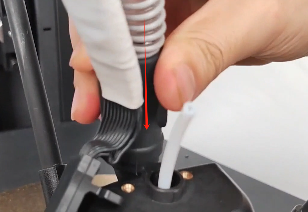
¶ 16. Push the effector line down and plug the effector line tightly, and fix it with M3×6 screws.
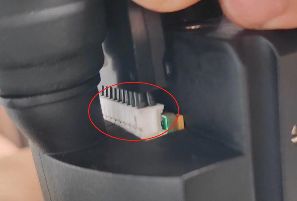
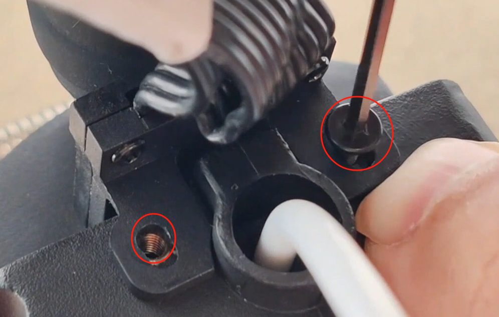
¶ 17. Take out the camera, place the camera parallel to the camera buckle, push it back and clamp it, and connect the camera cable to the type-c port.
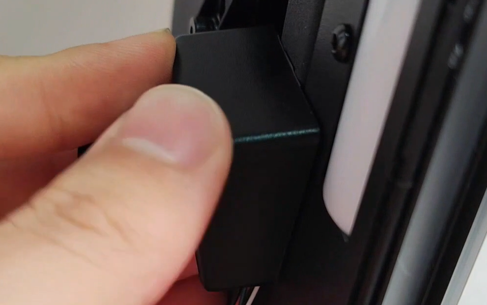
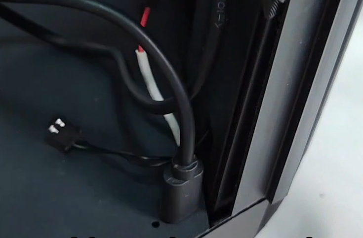
¶ 18. Plug the two wires of the LED light bar into each other, put the LED wire into the groove, and protect the wiring harness.
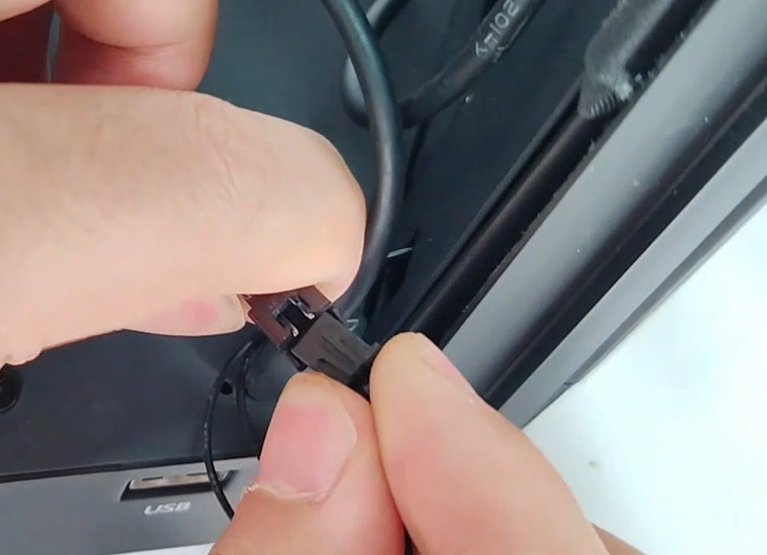
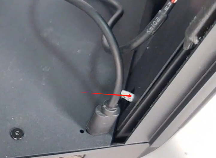
¶ 19. According to the label, insert the limit switch wires and motor wires of the three columns into the corresponding ports (please pay attention to the direction)
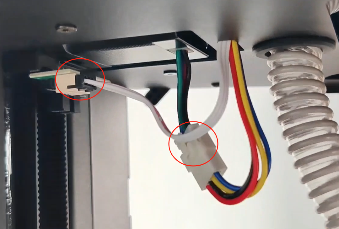
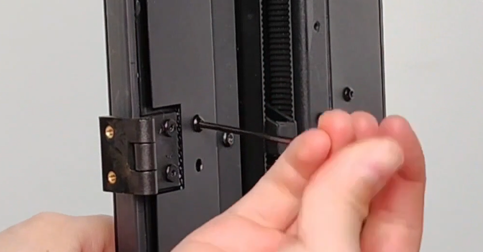
¶ 20. Use the H2.0 Allen wrench to remove the 3 ST2.9×16 screws on the X column cover plate, and remove the column X cover plate.
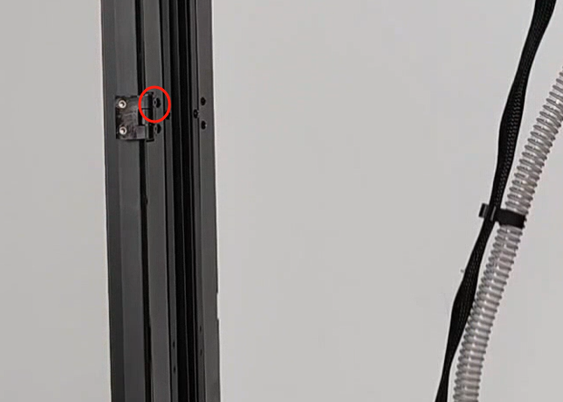
¶ 21. Straighten the main cable and type-c cable taken out from the groove of the lower shell upwards, and insert the main cable and type-c cable into the corresponding ports below the upper shell respectively.
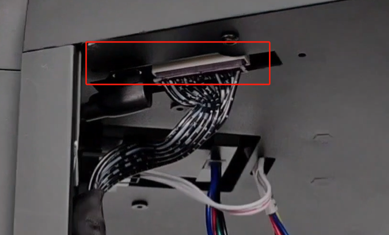
¶ 22. Take out the cable retainer, pinch the center buckle of the cable retainer and push it upward to gather the main cable and type-c cable.
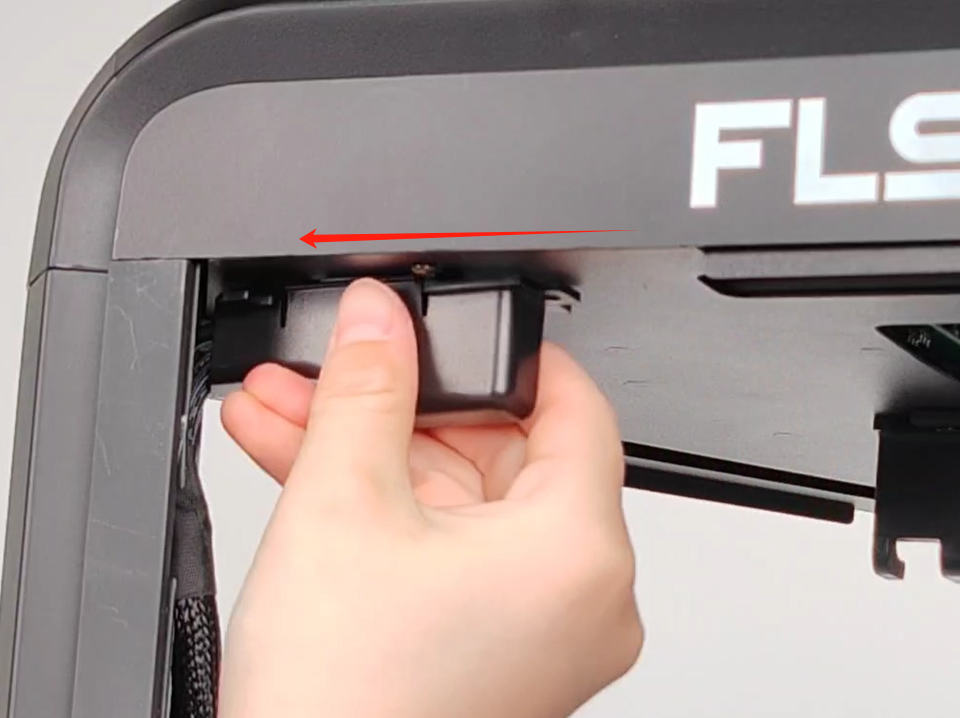
¶ 23. Put the column X cover plate back to the column X and fix it with ST2.9×16 screws.
¶ 24. Take out the display screen, gently push the black cable buckle upwards, push the display cable in and clamp it, and press the black buckle to fix the display cable (do not twist, flip, or bend the display cable)
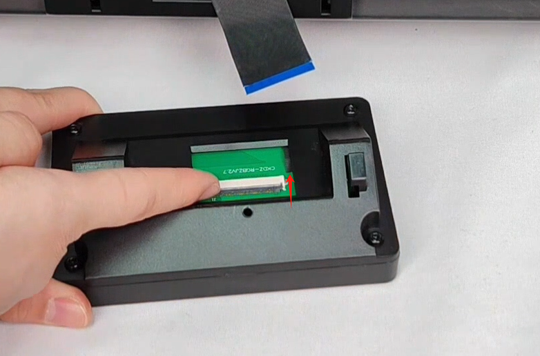
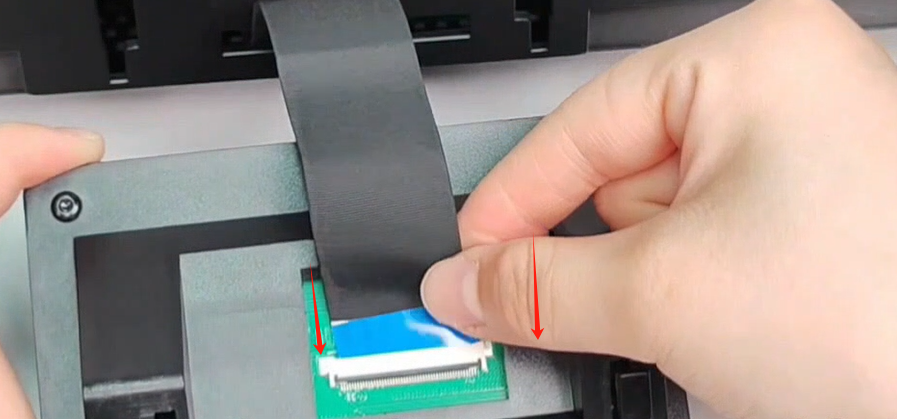
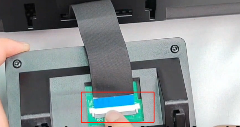
¶ 25. Push the display cable into the opening behind the screen, then insert the display back into the display slot, and push it down to clamp the display.
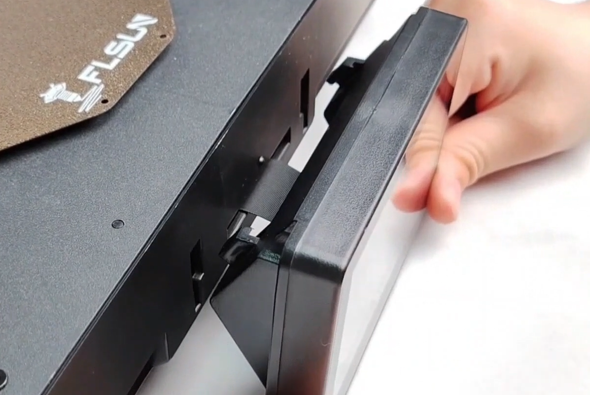
¶ 26. Take out the cover retaining frame and M3×6 screws and fix them.
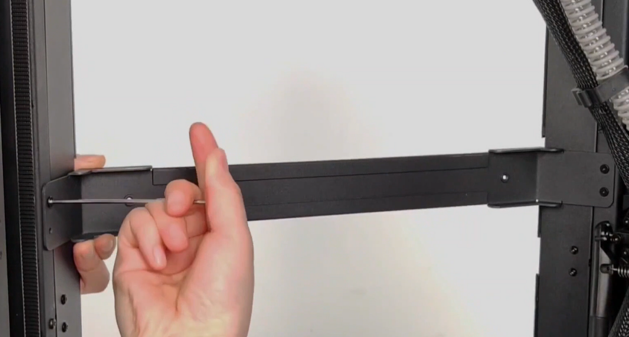
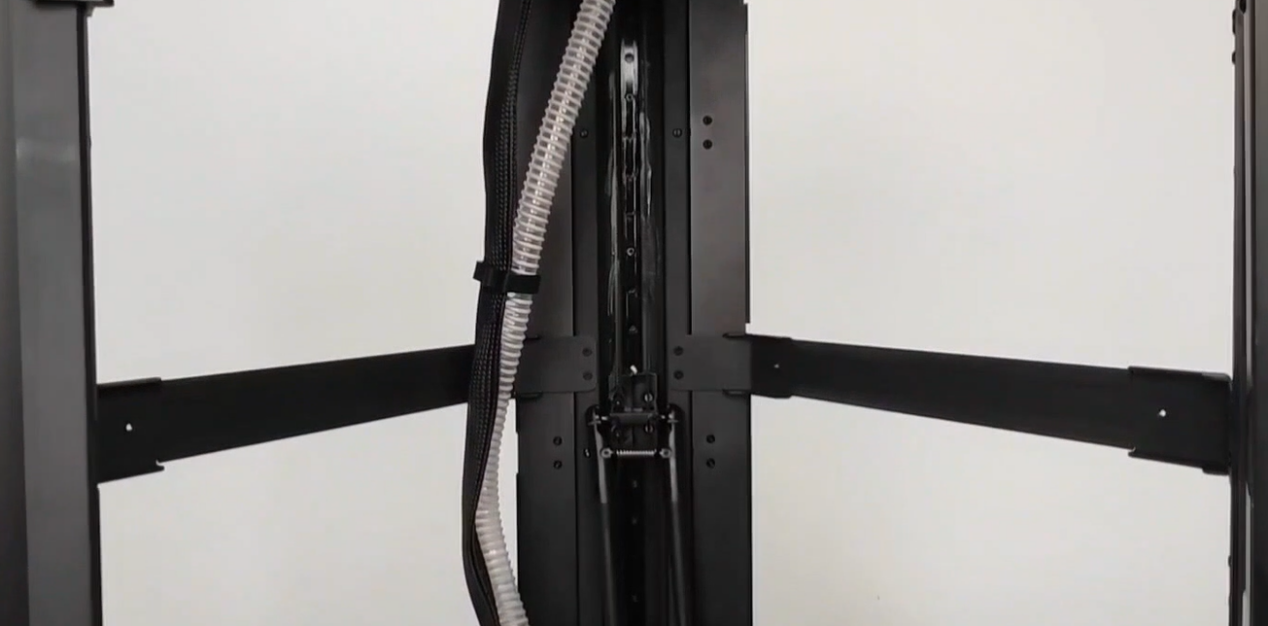
¶ 27. Take out the cover and tear off the protective film.
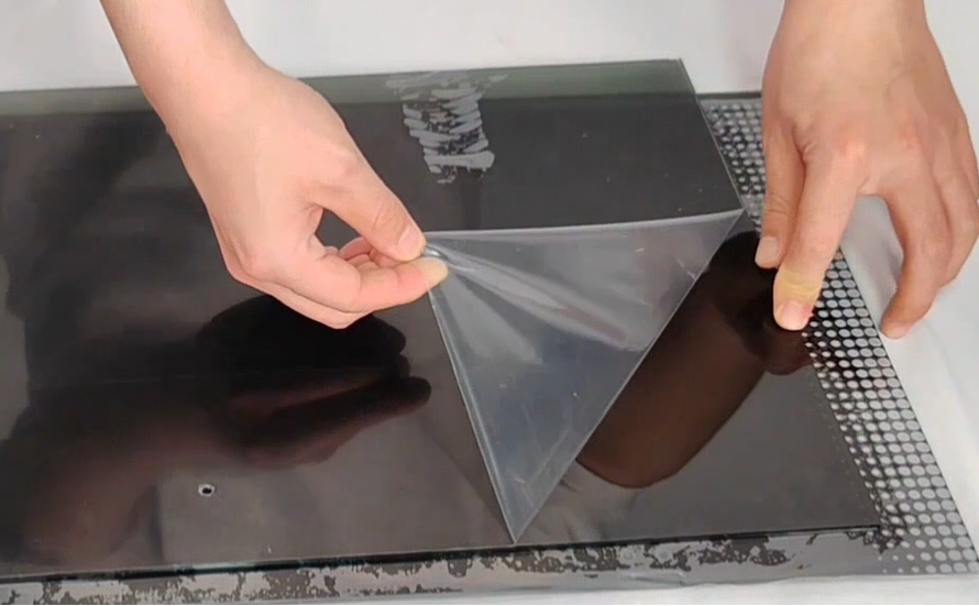
¶ 28. Install the side cover, put the cover in parallel, and then move the buckles on the upper and lower shells to clamp the cover.
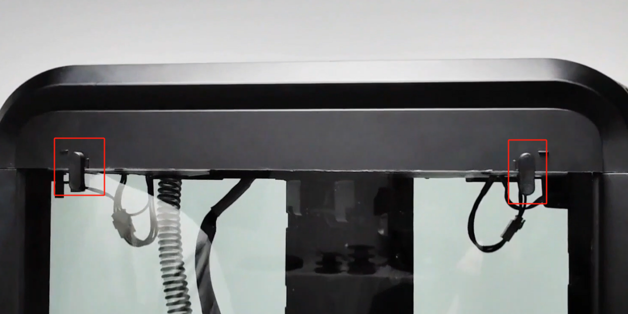
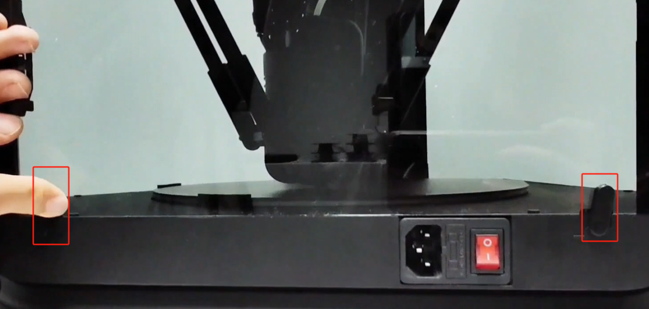
¶ 29. Use M3×6 screws to fix the side cover and beam.
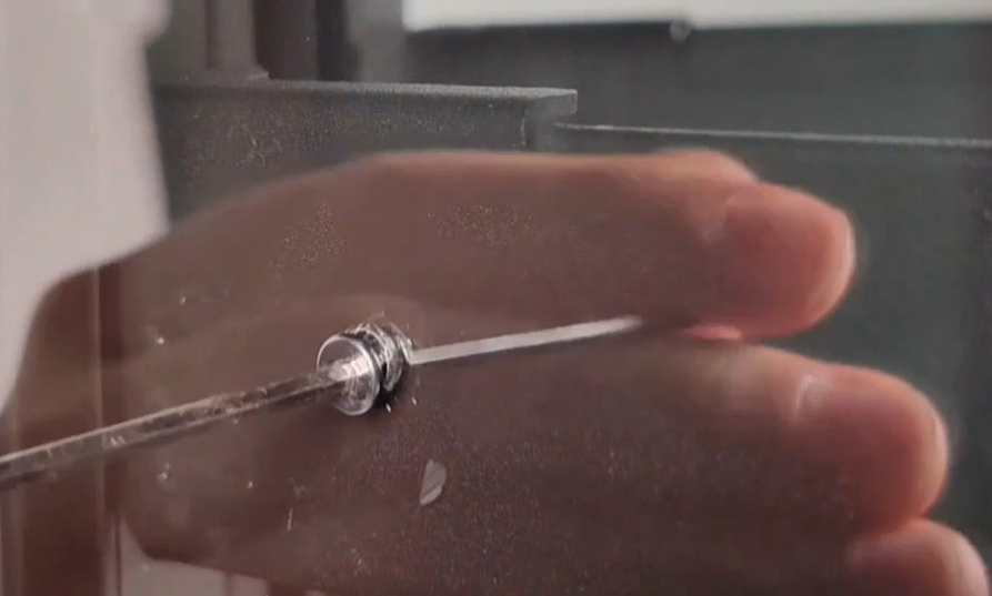
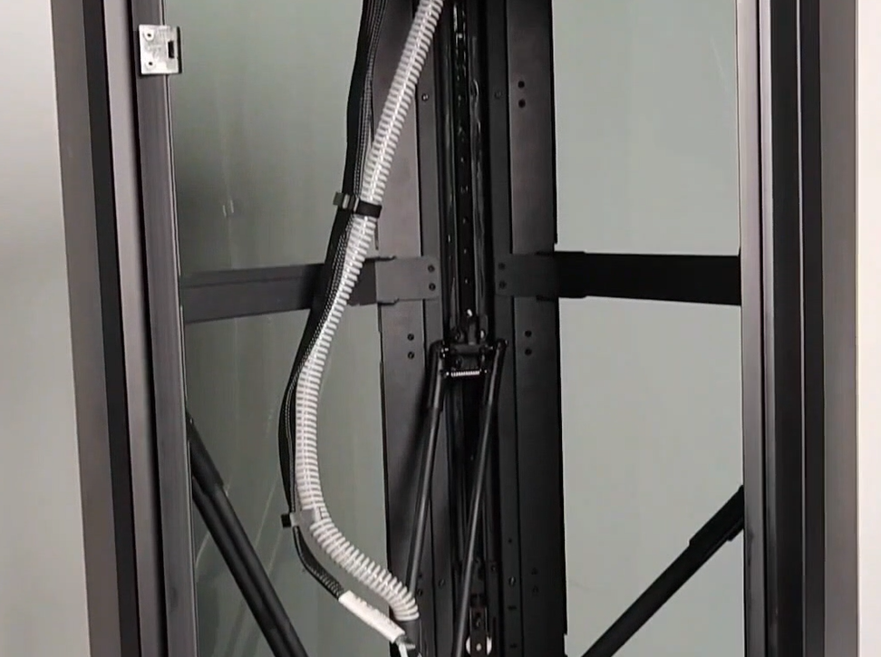
¶ 30. Install the front cover, align the front cover with the hinge screw hole on the column X, and fix it with M3×6 screws.
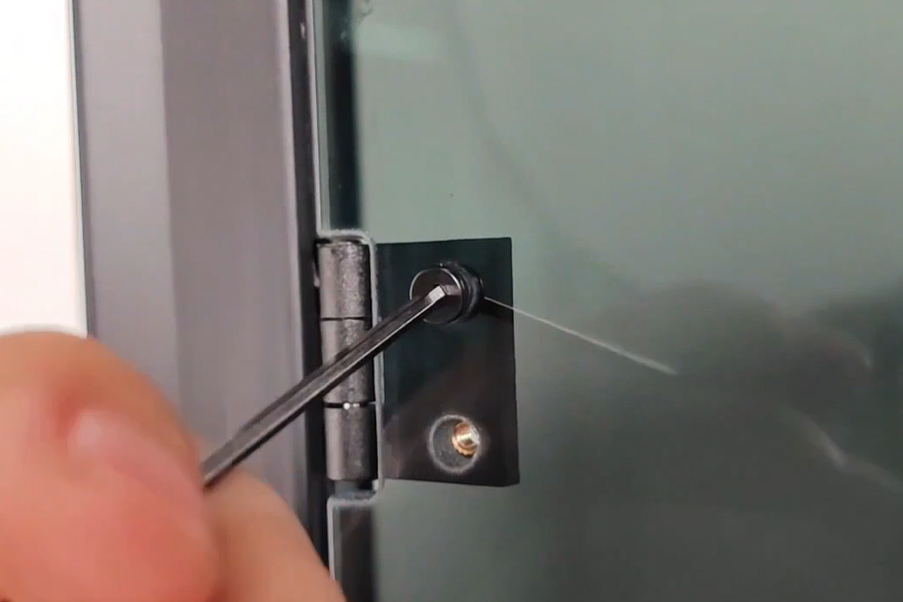
¶ 31. Use ST2.9×6 screws and T-type gaskets to fix the door handle.
